Troubleshooting loop detectors on high-traffic sites should follow a systematic process rather than replacing components by guesswork. Start by confirming the exact symptoms, then inspect the detector module, test loop resistance and continuity, check insulation resistance for ground faults, and examine the lead-in cable for physical damage. Electrical interference should also be ruled out before confirming that the loop detector is correctly connected and configured with the gate controller.
Inductive loop detectors are one of the most widely used vehicle detection technologies in commercial gate automation. Despite advances in access control and sensor technologies, loops remain reliable for vehicle presence detection at high-security sites. However, when faults occur, diagnosing the root cause is not always straightforward.
Effective gate loop detector troubleshooting requires a systematic approach that separates detector faults from cable faults, environmental issues, and integration problems. This guide explains how loop detectors work and outlines the seven key diagnostic steps experienced technicians follow.
How Loop Detectors Work in Automated Gate Systems
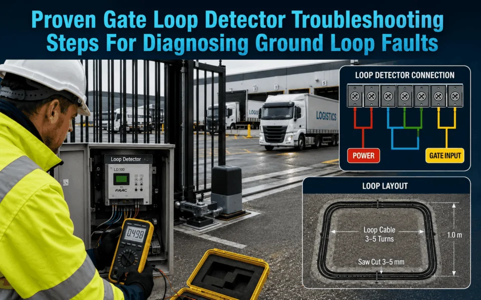
An inductive loop consists of wire embedded beneath the pavement surface. The loop forms part of an electrical circuit connected to a loop detector module located inside the gate controller cabinet.
The detector continuously monitors the loop’s inductance. When a vehicle passes over the loop, its metal mass alters the magnetic field generated by the loop, causing a measurable change in frequency. The detector interprets this change as vehicle presence and sends an output signal to the gate controller.
Because the system relies on precise frequency measurements, even small changes in cable integrity, insulation resistance, moisture levels, or electrical interference can affect performance.
Different loop types perform different functions within an automated gate system.
- Safety loops prevent gates from closing on vehicles occupying hazardous areas.
- Exit loops automatically trigger opening when vehicles approach from the inside.
- Presence loops maintain the gate open while a vehicle remains within the detection zone.
- Shadow loops provide additional safety coverage around moving gate leaves.
Constant vehicle movement increases mechanical stress on pavement surfaces. Heavy trucks generate higher loading forces than passenger vehicles. Frequent gate cycling creates greater wear on associated control systems. Environmental exposure, temperature changes, and moisture intrusion gradually affect insulation resistance and cable integrity.
As a result, gate loop detector troubleshooting on high-traffic sites often involves identifying faults that have developed gradually over many years of operation.
Read more: Gate Safety Sensors For High-Speed Automated Gates
What Common Loop Detector Symptoms Usually Mean
The behaviour of a vehicle loop can provide useful clues about where a fault is occurring. On high-traffic sites, recognising these symptoms early can help technicians narrow the diagnosis before disturbing pavement or replacing equipment.
- Detector stays permanently active. This can indicate a short circuit, damaged loop insulation, incorrect sensitivity settings or a vehicle/object remaining within the detection zone. Check the detector indicators and measure the loop circuit before assuming the detector module has failed.
- Vehicles are not detected. No detection may point to a broken loop wire, disconnected feeder cable, insufficient sensitivity or an incorrectly configured detector. Confirm loop continuity and detector settings, then test with different vehicle sizes.
- Detection is intermittent. Unreliable activation often suggests a deteriorating cable joint, loose terminal, damaged insulation or unstable loop connection. Vibration and temperature changes can make an existing wiring fault appear inconsistently.
- Fault appears after rain. Rain-related problems are a strong indication of moisture entering damaged loop insulation, joints or feeder cables. Resistance-to-earth testing can help identify insulation deterioration that may not be obvious during dry conditions.
- Adjacent traffic causes false detection. If vehicles in nearby lanes trigger the system, investigate excessive sensitivity, an oversized detection area, loop positioning or crosstalk between neighbouring loops. Adjusting detector frequency or sensitivity may help separate closely installed loops.
The 7-Step Gate Loop Detector Troubleshooting Process
When approaching any loop-related service call, technicians should follow a logical sequence of tests.
 Step gate loop detector troubleshooting process (AI-generated image; content provided by Digital Home Systems)
Step 1 – Confirm the Exact Fault Symptoms
The first step in gate loop detector troubleshooting is identifying precisely what the system is doing incorrectly.
Some loops remain permanently active, continuously indicating the presence of a vehicle. Others fail to detect vehicles altogether. Certain faults only appear intermittently, while some sites experience random gate activations without any vehicle present.
Before opening the control cabinet, gather information from site operators. Ask when the fault occurs, whether weather conditions influence operation, and whether recent construction work has taken place nearby. Reviewing event logs, observing gate behaviour, and collecting evidence before testing can significantly reduce diagnostic time later in the process.
Step 2 – Inspect the Loop Detector Module
Once the symptoms have been identified, inspect the detector module itself.
Most commercial loop detectors provide diagnostic LEDs that indicate power status, loop detection, fault conditions, and operating frequency. These indicators often provide immediate clues about whether the problem lies with the loop circuit or the detector.
Check detector sensitivity settings to ensure they remain appropriate for the vehicle types using the site. Incorrect sensitivity can create missed detections or nuisance triggering.
Frequency settings should also be reviewed, particularly on sites with multiple adjacent loops. Improper frequency separation can cause crosstalk between loops, leading to unstable operation.
Step 3 – Check Loop Resistance and Continuity
After confirming detector operation, attention should shift to the loop wiring itself. Using a quality multimeter, disconnect the loop from the detector and measure loop resistance.
Most loops exhibit relatively low resistance, typically ranging from a few to several tens of ohms, depending on cable length and loop size. Exact values vary by installation design.
An open circuit reading usually indicates a broken conductor somewhere within the loop or lead-in cable. A short circuit reading suggests damaged insulation, causing conductor contact.
Record all measurements carefully. Historical records provide valuable comparisons during future maintenance visits. In addition, continuity testing alone does not guarantee a healthy loop, but it provides an important starting point for identifying obvious cable faults.
Step 4 – Test Insulation Resistance to Identify Ground Faults
Ground faults are among the most common causes of difficult-to-diagnose loop problems.
Even when continuity and resistance measurements appear normal, insulation breakdown can create unstable operation, false triggering, or permanent presence detection.
A megohmmeter, commonly known as a Megger, should be used to test insulation resistance between loop conductors and earth.
Healthy loops generally exhibit very high insulation resistance values. Lower readings often indicate moisture ingress, cable degradation, or damaged insulation.
On older installations, water penetration into pavement cuts frequently causes insulation values to deteriorate over time. Seasonal weather changes may explain why faults appear only during wet conditions.
When insulation resistance falls below acceptable levels, cable replacement often becomes more economical than repeated repairs.
For many experienced technicians, insulation testing is the most important step in gate loop detector troubleshooting because it frequently identifies faults that basic continuity tests miss.

Step 5 – Examine Loop Lead-In Cable Integrity
The loop itself may be intact while the lead-in cable connecting it to the detector is damaged.
Inspect conduit systems for cracking, crushing, or water ingress. Examine junction boxes for signs of corrosion, contamination, or poor termination practices.
Rodent damage is a surprisingly common cause of intermittent faults in industrial environments. Construction works may also damage buried conduit without operators realising the impact on detection systems.
Lead-in cables running beneath driveways are particularly vulnerable to mechanical damage caused by ground movement and repeated vehicle loading. Any signs of insulation deterioration, exposed conductors, or compromised splices should be addressed immediately.
Step 6 – Identify Electrical Interference Sources
Not all loop faults originate within the loop circuit itself. Electrical interference can create symptoms that closely resemble cable failures.
Potential interference sources include nearby power cables, motor control systems, variable frequency drives (VFDs)(1 Variable frequency drives (VFDs).Date of access on 17/08/2026↓), pumps, compressors, and large industrial machinery.
Adjacent loop systems may also interact when their frequency settings overlap. Where interference is suspected, temporarily adjusting detector frequencies can help isolate the problem. Some advanced detectors include automatic frequency tuning functions designed to minimise crosstalk.
Documenting interference sources during gate loop detector troubleshooting helps prevent recurring issues during future upgrades.
Step 7 – Verify Gate Controller and System Integration
The final step in gate loop detector troubleshooting involves confirming correct integration between the detector and the gate controller.
Test detector outputs independently from the gate controller. Verify that relays operate correctly and that controller inputs receive the expected signals. Also, review gate logic programming to ensure safety loops, presence loops, and exit loops are configured correctly.
In some cases, detector operation may be perfectly normal, while incorrect controller programming can create unexpected gate behaviour.

What are Common Ground Loop Faults Found on High-Traffic Sites?
The table below summarises some of the most common faults encountered during gate loop detector troubleshooting projects.
| Fault Type | Typical Cause | Common Symptoms | Recommended Fix |
| Water ingress | Damaged sealant | Intermittent triggers | Reseal or replace loop |
| Insulation breakdown | Age and moisture | False presence detection | Replace cable |
| Lead-in cable damage | Construction works | Random operation | Repair cable |
| Open loop | Broken conductor | No detection | Reinstall loop |
| Electrical interference | Nearby services | Unstable operation | Frequency adjustment |
| Poor splices | Corrosion | Intermittent faults | Re-terminate connections |
What are Advanced Diagnostic Techniques Experienced Installers Use?
Standard electrical tests identify most loop faults. However, complex sites may require advanced testing to separate detector faults, cable problems, electrical interference and controller issues.
- Analyse loop operating frequency: Use a frequency meter or detector diagnostic display to compare adjacent loops. Loops operating at similar frequencies may interfere with each other and cause crosstalk, false detection or intermittent activation. Adjust the frequency settings and retest the system.
- Monitor the signal with an oscilloscope: An oscilloscope can reveal signal fluctuations, electrical noise and unstable oscillation that may not appear during a standard resistance test. This is particularly useful where faults occur only while nearby equipment is operating.
- Measure loop inductance: Record the inductance of each loop and compare the readings with the detector’s operating range and other loops of a similar size. An unusual result may indicate damaged conductors, incorrect loop geometry, poor joints or an excessively long lead-in cable.
- Compare readings across the site: Where several loops are installed, use known working loops as reference points. Significant differences in resistance, insulation resistance, inductance or frequency can quickly identify the abnormal circuit.
- Use thermal imaging selectively: A thermal camera may help locate unusual heat around accessible cables, junction boxes or damaged connections. However, it is generally less reliable for deeply buried loop faults and should support, rather than replace, electrical testing.
- Substitute a known-good detector: Temporarily install a compatible detector that is confirmed to be working. If the fault disappears, the original detector is likely defective. If the fault remains, continue investigating the loop, lead-in cable, interference sources and controller inputs. The US Federal Highway Administration includes electronics-unit substitution as a recognised loop troubleshooting method.
- Isolate external equipment: Temporarily switch off nearby motors, pumps, variable frequency drives or other high-current equipment where safe and permitted. If the loop stabilises, reconnect each device individually to identify the interference source.
The US Federal Highway Administration(2 The US Federal Highway Administration.Date of access on 17/08/2026↓) reports that when a failed traffic loop forces a signal phase into maximum recall, intersection delay can increase by 50% or more. Although this figure relates to traffic-signal loops, it demonstrates how a single unresolved detector fault can significantly disrupt an automated access or traffic-control system.

Installation Errors That Cause Repeat Loop Detector Callouts
Many recurring loop detector faults are caused by poor installation practices rather than failed equipment.
- Incorrect loop geometry: Loops that are the wrong size, shape or position may detect vehicles inconsistently. Poor geometry can also create weak detection zones or unwanted activation from nearby traffic.
- Excessive lead-in cable length: Long lead-in cables increase resistance and make the circuit more vulnerable to electrical interference. Keep cable runs as short and direct as practical.
- Insufficient twisting of lead-in conductors: The lead-in wires should be tightly and evenly twisted to reduce electromagnetic interference. Loose or inconsistent twisting can cause unstable detection and nuisance triggering.
- Incorrect or inadequate sealant: Sealants that crack, shrink or separate from the pavement allow moisture to enter the saw cut. Water ingress can reduce insulation resistance and create intermittent faults, especially during wet weather.
- Loop cables installed near mains power: Running loop wiring parallel to power cables, motors or high-current circuits can introduce electrical noise. Maintain suitable separation and cross power cables at right angles where possible.
- Poorly protected junction boxes: Junction boxes without suitable weather and moisture protection may develop corrosion, contaminated terminals and damaged connections. Use correctly rated enclosures and sealed cable entries.
- Incorrect sensitivity settings: Sensitivity set too high can cause false or nuisance detections. Sensitivity set too low may prevent the system from detecting smaller or higher-clearance vehicles.
- Poor-quality cable joints or splices: Unsealed or poorly terminated joints can introduce resistance, moisture and intermittent continuity. Avoid unnecessary joints and use approved waterproof connection methods where splicing is unavoidable.
At DHS, we have seen recurring loop detector callouts where the detector itself was not the real problem. In several commercial gate projects, intermittent faults were traced back to issues such as moisture entering underground cable joints, poorly sealed saw cuts, damaged lead-in cables, incorrect sensitivity settings or electrical interference from nearby equipment. In these cases, replacing the detector alone would not have provided a lasting fix. It requires the complete loop circuit, cable condition, detector settings and gate controller integration so the underlying cause can be corrected.
How to Strategically Prevent Loop Detector Failures on High-Traffic Sites
Regular preventative maintenance can reduce emergency callouts, improve detection reliability and extend the service life of gate loop systems.
- Test insulation resistance annually: Periodic Megger testing can identify moisture ingress, insulation breakdown and developing ground faults before they disrupt gate operation.
- Inspect pavement and loop cuts: Check for cracked sealant, surface movement, damaged saw cuts and signs of water penetration. Early repairs can prevent further cable deterioration.
- Check junction boxes and terminations: Inspect enclosures for moisture, corrosion, loose terminals and damaged cables. Clean, reseal or replace affected components before intermittent faults develop.
- Review detector settings: Confirm that sensitivity, presence time and frequency settings remain suitable for site conditions and vehicle types. Settings may need adjustment after equipment or traffic-flow changes.
- Analyse event logs: Repeated false detections, missed activations or unusual gate cycles may indicate a developing fault. Reviewing logs helps technicians identify patterns before a complete failure occurs.
- Retest after civil works: Perform resistance, insulation and operational testing after resurfacing, trenching, drainage works or nearby construction. These activities can damage loops or lead-in cables without obvious surface evidence.
- Maintain service records: Record test results, detector settings, repairs and site changes at every visit. Comparing current readings with previous results makes gradual deterioration easier to identify.
Read more: How Automatic Gate Systems Are Installed For Commercial Properties

When to Repair, Re-Cut, or Replace the Loop System
Minor junction box issues, damaged terminations, and isolated lead-in cable faults can often be repaired economically. Short cable sections may sometimes be replaced without disturbing the entire loop.
However, widespread insulation breakdown, extensive water damage, repeated intermittent faults, or multiple conductor failures often indicate that full loop replacement is the most cost-effective solution.
Digital Home Systems (DHS) can assess the loop circuit, detector module, lead-in cable, and gate controller integration to determine whether repair, re-cutting, or complete replacement is the most practical option.
Replacement projects also provide an opportunity to evaluate newer detector technologies, improve installation practices, and upgrade system documentation to simplify future maintenance.
In Conclusion
Reliable vehicle detection is essential for safe and efficient gate automation, particularly on busy commercial sites. Effective gate loop detector troubleshooting involves a structured process that examines detector settings, loop integrity, insulation resistance, electrical interference, and controller integration.
By following these proven diagnostic steps, installers and service technicians can identify the true cause of faults faster and significantly reduce repeat callouts.
If you’re planning a commercial gate upgrade or seeking expert support for automated gate systems, contact DHS. Our team provides professional gate & door automation solutions and industry-leading expertise to help keep your access systems operating safely and reliably.
FAQs
Permanent activation is commonly caused by insulation breakdown, moisture ingress, detector failure, electrical interference, or a vehicle remaining within the detection area. Ground faults are often the primary cause on older installations.
Most detectors include diagnostic LEDs and status indicators that allow technicians to verify operation while installed. Resistance, continuity, and insulation testing can also be performed from the controller cabinet after disconnecting the loop.
Yes. Water ingress is one of the most common causes of intermittent operation. Moisture can reduce insulation resistance, leading to unstable frequency readings and false alarms.
Acceptable values vary by manufacturer, but healthy loops generally exhibit very high insulation resistance readings. Significantly reduced readings often indicate moisture ingress or insulation deterioration requiring further investigation.
Properly installed loops can operate reliably for 10 to 20 years or longer. Lifespan depends heavily on traffic volume, environmental conditions, pavement quality, and maintenance practices.